http://decadeengine.blogspot.com/
How to generate a procedural sphere.
The base of my generated sphere is a cube. Depending on how smooth the generated sphere needs to be, I recursively split each side into 4 equally sized children. This is achieved my finding the center of the face, popping that point out so that it is the correct radius from the center, then making 4 faces using the original points and this new point. (There is some ASCII art showing this in the code below)
void CSphere::Initialize(float p_fRadius, int p_iMaxDepth)
{
// TLB----TRB
// /| /|
// / | / |
// TLF----TRF |
// | BLB--|BRB
// | / | /
// | / |/
// BLF----BRF
//Putting the Vertices of the initial Cube at p_fRadius is not correct as the distance of
//p_fRadius, p_fRadius, p_fRadius from the Origin is greater than p_fRadius.
CVector3 l_Vertices[8];
l_Vertices[TOP_LEFT_FRONT] = MoveToRadiusDistance(CVector3(-p_fRadius, p_fRadius, -p_fRadius), p_fRadius);
l_Vertices[TOP_RIGHT_FRONT] = MoveToRadiusDistance(CVector3( p_fRadius, p_fRadius, -p_fRadius), p_fRadius);
l_Vertices[BOTTOM_RIGHT_FRONT] = MoveToRadiusDistance(CVector3( p_fRadius, -p_fRadius, -p_fRadius), p_fRadius);
l_Vertices[BOTTOM_LEFT_FRONT] = MoveToRadiusDistance(CVector3(-p_fRadius, -p_fRadius, -p_fRadius), p_fRadius);
l_Vertices[TOP_LEFT_BACK] = MoveToRadiusDistance(CVector3(-p_fRadius, p_fRadius, p_fRadius), p_fRadius);
l_Vertices[TOP_RIGHT_BACK] = MoveToRadiusDistance(CVector3( p_fRadius, p_fRadius, p_fRadius), p_fRadius);
l_Vertices[BOTTOM_RIGHT_BACK] = MoveToRadiusDistance(CVector3( p_fRadius, -p_fRadius, p_fRadius), p_fRadius);
l_Vertices[BOTTOM_LEFT_BACK] = MoveToRadiusDistance(CVector3(-p_fRadius, -p_fRadius, p_fRadius), p_fRadius);
//Initialize the faces of the cube (The face structure just stores the vertices for the face corners and has render functionality, not applicable to this explanation, and its depth in the face tree)
m_pFaces[FRONT].Initialise(FRONT, l_Vertices[TOP_LEFT_FRONT], l_Vertices[TOP_RIGHT_FRONT], l_Vertices[BOTTOM_RIGHT_FRONT], l_Vertices[BOTTOM_LEFT_FRONT], DEPTH0);
m_pFaces[RIGHT].Initialise(RIGHT, l_Vertices[TOP_RIGHT_FRONT], l_Vertices[TOP_RIGHT_BACK], l_Vertices[BOTTOM_RIGHT_BACK], l_Vertices[BOTTOM_RIGHT_FRONT], DEPTH0);
m_pFaces[BACK].Initialise(BACK, l_Vertices[TOP_RIGHT_BACK], l_Vertices[TOP_LEFT_BACK], l_Vertices[BOTTOM_LEFT_BACK], l_Vertices[BOTTOM_RIGHT_BACK], DEPTH0);
m_pFaces[LEFT].Initialise(LEFT, l_Vertices[TOP_LEFT_BACK], l_Vertices[TOP_LEFT_FRONT], l_Vertices[BOTTOM_LEFT_FRONT], l_Vertices[BOTTOM_LEFT_BACK], DEPTH0);
m_pFaces[TOP].Initialise(TOP, l_Vertices[TOP_LEFT_BACK], l_Vertices[TOP_RIGHT_BACK], l_Vertices[TOP_RIGHT_FRONT], l_Vertices[TOP_LEFT_FRONT], DEPTH0);
m_pFaces[BOTTOM].Initialise(BOTTOM, l_Vertices[BOTTOM_LEFT_FRONT], l_Vertices[BOTTOM_RIGHT_FRONT], l_Vertices[BOTTOM_RIGHT_BACK], l_Vertices[BOTTOM_LEFT_BACK], DEPTH0);
//Subdivide each patch to the lowest resolution
m_pPatches[FRONT].SubDivide(p_fRadius, p_iMaxDepth);
m_pPatches[RIGHT].SubDivide(p_fRadius, p_iMaxDepth);
m_pPatches[BACK].SubDivide(p_fRadius, p_iMaxDepth);
m_pPatches[LEFT].SubDivide(p_fRadius, p_iMaxDepth);
m_pPatches[TOP].SubDivide(p_fRadius, p_iMaxDepth);
m_pPatches[BOTTOM].SubDivide(p_fRadius, p_iMaxDepth);
}
where
bool CSphereFace::SubDivide(float p_fRadius, int p_iMaxDepth)
{
if (m_iDepth >= p_iMaxDepth)
return false;
//Create the Additional Vertices
//
// NW---------------D-------------NE
// | | |
// | | |
// | | |
// | | |
// A--------------Center-----------C
// | | |
// | | |
// | | |
// | | |
// SW----------------B-------------SE
//
//
g_vAdditionalVertices[A] = m_vBaseVertices[eNorthWest] + ((m_vBaseVertices[eSouthWest] - m_vBaseVertices[eNorthWest]) / 2.0f);
g_vAdditionalVertices[B] = m_vBaseVertices[eSouthWest] + ((m_vBaseVertices[eSouthEast] - m_vBaseVertices[eSouthWest]) / 2.0f);
g_vAdditionalVertices[C] = m_vBaseVertices[eNorthEast] + ((m_vBaseVertices[eSouthEast] - m_vBaseVertices[eNorthEast]) / 2.0f);
g_vAdditionalVertices[D] = m_vBaseVertices[eNorthWest] + ((m_vBaseVertices[eNorthEast] - m_vBaseVertices[eNorthWest]) / 2.0f);
//Create Child Nodes
m_pChildren = new CSphereFace[4];
m_pChildren[eNorthWest].Initialise(eNorthWest, m_vBaseVertices[eNorthWest], g_vAdditionalVertices[D], m_vBaseVertices[eCentre], g_vAdditionalVertices[A], m_iDepth + 1);
m_pChildren[eNorthEast].Initialise(eNorthEast, g_vAdditionalVertices[D], m_vBaseVertices[eNorthEast], g_vAdditionalVertices[C], m_vBaseVertices[eCentre], m_iDepth + 1);
m_pChildren[eSouthWest].Initialise(eSouthWest, g_vAdditionalVertices[A], m_vBaseVertices[eCentre], g_vAdditionalVertices[B], m_vBaseVertices[eSouthWest], m_iDepth + 1);
m_pChildren[eSouthEast].Initialise(eSouthEast, m_vBaseVertices[eCentre], g_vAdditionalVertices[C], m_vBaseVertices[eSouthEast], g_vAdditionalVertices[B], m_iDepth + 1);
m_pChildren[eNorthWest].SubDivide(p_fRadius, p_iMaxDepth);
m_pChildren[eNorthEast].SubDivide(p_fRadius, p_iMaxDepth);
m_pChildren[eSouthWest].SubDivide(p_fRadius, p_iMaxDepth);
m_pChildren[eSouthEast].SubDivide(p_fRadius, p_iMaxDepth);
return true;
}
and
CVector3 MoveToRadiusDistance(CVector3 p_Vector, float p_fRadius)
{
//Get the Normalized Vector, of this vertex from the origin (center of the sphere) and pop it out to the correct radius,
return p_Vector.Normalize() * p_fRadius;
}
That is pretty much the basics of how I create the sphere from recursively subdividing a cube. If I overlooked anything please comment and I will correct the post to reflect any gap in information or any mistake.
I shall try and highlight an area which is
- Easier to implement
- Less code
- More efficient
#define SQUARE(x) ((x)*(x))
float Length(CVector3* p_pvOne, CVector3* p_pvTwo)
{
return (float)(sqrt(SQUARE(pvTwo->X - p_pvOne->X) + SQUARE(pvTwo->Y - p_pvOne->Y) + SQUARE(pvTwo->Z - p_pvOne->Z)));
}
(The sqrt function has been traditionally considered slow and avoided if possible. I am unsure of its performance on modern hardware however the above could be optimised by not calculating the sqrt in the length function, and comparing it to the expected value squared.)
An better optimisation is to remove the requirement for calculating the distance from each patch to the centre of LOD completely. Instead of using the distance from the centre, I now recursively step from the centre to each neighbour, then onto each of their neighbours while incrementing the 'distance' with each step. When the 'distance' reaches a predefined value, the edge of the LOD area has been reached. In the following images 'distance limit' is set to 3.
The results above are not as desired. Some analysis showed that the east and west neighbours of the centre of LOD are within 3 recursive steps from the north neighbour (which is processed first). Because of this the east and west patches are marked as processed and will not be processed again when directly updated from the centre patch.
To overcome this, when processing a patch, if it is already flagged as processed, I compare its distance in steps from the centre of LOD. If the current distance is less than the stored distance I process again. Reading that sounds a little confusing so I shall try and explain in some steps. (only key steps are listed)
- Move from the centre patch to the north. Its distance is stored as 1
- Move from the current patch (north) to the east. Distance is stored as 2
- Move from the current patch (north->east) to the south (this is the centres east neighbour). Distance is stored as 3.
- Move from the centre patch to the east. This patch is flagged as processed at a distance of 3. The current distance is 1 therefore ignore previous processing and process again.


The above example has resulted in code which is smaller, simpler to understand and faster to run than the previous version based on actual distance.
 |
| Planet rendered from orbit showing LOD |
 |
| Same planet rendered from atmosphere, again showing LOD |
"Using frustum culling is not enough to remove any unrendered polygons from the planet. When close to a planet it can look like a flat terrain, just like the earth does for us as we stand on it, but from height it can be seen that the planet is in-fact spherical. With this knowledge it is possible to mathematically remove allot of the planet patches which are on the opposite side of the planet. With Back face culling the API would remove these anyway, however it would be very wasteful to pass these invisible faces down the render pipeline. By using a DotProduct with the LookAt vector of the camera and the Normal of the planet patch translated to model space, it is very simple to ignore these patches."
This code was part of what was lost from Decade with the recient SVN blooper, and therefore had to be rewritten. Despite having implemented the functionality about 18 months ago it took me some time to grasp the idea. I feel that a more technical post would be useful and will hopefully help anyone else when implementing similar functionality.
Anyone with experience in graphics programming will be familar with the concept of backface culling. As each polygon is passed down the rendering pipeline, it is tested to see if it is facing torwards or away from the camera. Since polygons facing away from the camera cannot be seen there is no need to render them. This concept can be applied when rendering a planet, however instead of just testing on a polygon by polygon basis, I test patch by patch. This allows me to ignore large collections of polygons with 1 test instead of the previously described polygon test.
How is this achieved?
Two pieces of information are required in order to test if a patch is facing towards or away from the camera.
1) The camera look-at vector. This is maintained by the camera object and updated as the camera moves and rotates around the world.
2) The normal vector of the patch. I calculate this when the patch is created by doing a CrossProduct of the vectors of 2 sides of the patch.

If the values of A,B,C and D in the above image are
l_vA: X=-11.547007 Y=11.547007 Z=-11.547007
l_vB: X=-6.6666670 Y=13.333334 Z=-13.333334
l_vC: X=-8.1649666 Y=8.1649666 Z=-16.329933
l_vD: X=-13.333334 Y=6.6666670 Z=-13.333334
The normal of the patch can be calculated using the following code.
m_vNormal = CalculateNormal(l_vB, l_vA, l_vC);
where
CVector3 CalculateNormal(CVector3 p_vOne, CVector3 p_vTwo, CVector3 p_vThree)
{
CVector3 l_vA = p_vTwo - p_vOne;
CVector3 l_vB = p_vThree - p_vOne;
return Normalize(CrossProduct(l_vA, l_vB));
}
CVector3 CrossProduct(CVector3 p_vVectorOne, CVector3 p_vVectorTwo)
{
CVector3 l_vResult;
l_vResult.X = p_vVectorOne.Y * p_vVectorTwo.Z - p_vVectorOne.Z * p_vVectorTwo.Y;
l_vResult.Y = p_vVectorOne.Z * p_vVectorTwo.X - p_vVectorOne.X * p_vVectorTwo.Z;
l_vResult.Z = p_vVectorOne.X * p_vVectorTwo.Y - p_vVectorOne.Y * p_vVectorTwo.X;
return l_vResult;
}
The calculated normal would be X=0.44721335 Y=-0.44721335 Z=0.77459687
With this information, as each patch is rendered, a simple DotProduct of these 2 pieces of information returns a floating point value. If this value is less than 0, the patch is facing away from the camera and therefore it and all its child patches can immediately be discarded.
float l_fDotProduct = DotProduct(m_vNormal, p_pCamera->get_LookAt());
if (0.0f > l_fDotProduct)
return;
where
float DotProduct(CVector3 p_vVectorOne, CVector3 p_vVectorTwo)
{
return p_vVectorTwo.X * p_vVectorOne.X + p_vVectorTwo.Y * p_vVectorOne.Y + p_vVectorTwo.Z * p_vVectorOne.Z;
}
One more issue must be dealt with before we have a complete solution. The above works well for static objects where all vertices are relative to the origin. However what will happen if the object is rotating?
The answer of that question is shown in the following image.

It may not be obvious from an image instead of a realtime demo so I will try and explain. The above implemented patch culling is processed on
the raw sphere data. This is equilavent to removing back-facing patches (anything from the back of the sphere, relative to the camera, is removed), then rotating the sphere on the Y axis (in the image above
the sphere is rotated by 130 degrees) and then rendering with the API culling all back-facing polygons. This order is obviously incorrect.
The more correct sequence would be to rotate the sphere, remove all back-facing patches, then render remaining patches and allow the API to remove any back-facing polygons in the front-facing patches. Since rotation occurs in the render pipeline it isn't possible for us to rotate before we remove the back-facing patches.
The solution is to multiply the camera look-at vector by the modelview matrix. This is equilavent to transforming the camera by the same values that will be applied to the sphere, resulting in the correct back-facing patches being removed, regardless of what rotation/translation/scaling is applied to the sphere.
float l_fDotProduct = DotProduct(m_vNormal, p_pCamera->get_LookAt() * p_pGraphics->get_Matrix(eModelView));
if (0.0f > l_fDotProduct)
return;
(Note: Since p_pCamera->get_LookAt() * p_pGraphics->get_Matrix(eModelView) will yield the same value for every patch, it would be better to calculate this once per frame for each planet that is being rendered. This value can then be used within the test on each patch in the planet.)
This means that I have to recode those sections. A chore, but on a positive side, I know the pit-falls and issues I encountered the last time, and can hopefully design around these and end up with better solution.
As per my previous post, I have also started IPhone and Android development. I shall be working on multiple projects at the same time, and rather than mix it all up on this blog, I have created a sister blog to this for Decade Mobile. Any updates which are specific to the mobile platforms shall be posted there.
Development of Decade shall continue as before with procedural planery bodies, but over the past few months I have started to program IPhone/IPad and Android, therefore I think it would be fun to create a mobile Decade Engine and try to make some simple but fun phone games.
Let the adventure begin (yet again!)
Ciarán
Ciarán
Let’s take some time to recap what needs to be procedurally generated in order to render the planet (shown in the video below).
Permutations Texture
The topography of the planet is created using noise algorithms. This example uses Multi Ridged Brownian Fractal Motion. At runtime this noise is created using a series of permutations which are stored in a texture so that it can be accessed by in a shader. The texture data doesn’t make allot of visual sense, however here is an example of what it looks like.

1 Vertex buffer
The planet is rendered as a series of patches. It is this patch nature which allows the recursive sub-division resulting in the increased/decreased level of visible detail. Whereas the CPU Planet generates a unique vertex buffer for each patch (because the noise is calculated when the patch is created and applied to height data in the vertex buffer), the GPU Planet only uses 1 vertex buffer of X * X vertices, generated procedurally, which are displaced in a shader at runtime for each patch to be rendered.

16 Index Buffers
An index buffer is used along with a vertex buffer to render some geometry. In allot of cases 1 vertex buffer is used with 1 index buffer. As described in previous posts a terrain requires 16 index buffers, generated procedurally, so that there are no terrain cracks. It must be possible for the edges of terrain patches, with different levels of detail, to join together seamlessly.

In the video above shows a basic GPU Planet. There is quiet an obvious bug visible as the camera moves. Because all noise is generated on the GPU, the Decade Engine running on the CPU has no knowledge of how much a vertex is displaced. All distance checking from the camera to the planet is calculated from the camera position to the underlying sphere of the planet (vertex displaced to radius of the planet but not with height noise applied). This is ok when the camera is high above the terrain however as the camera moves close to the surface, especially if this ground is at a high altitude, the sphere position may still be some distance beneath and therefore terrain subdivision do not occur properly.
I am considering 2 possible techniques to over come this
- Generate the same noise values on the CPU as is generated on the GPU. Since all (pseudo) random data is stored in the permutations texture, it should be possible.
- Render the height data to a texture instead of generating it as required each frame, then use this texture for shader vertex displacement as well as calculating the height of key vertices on the CPU.

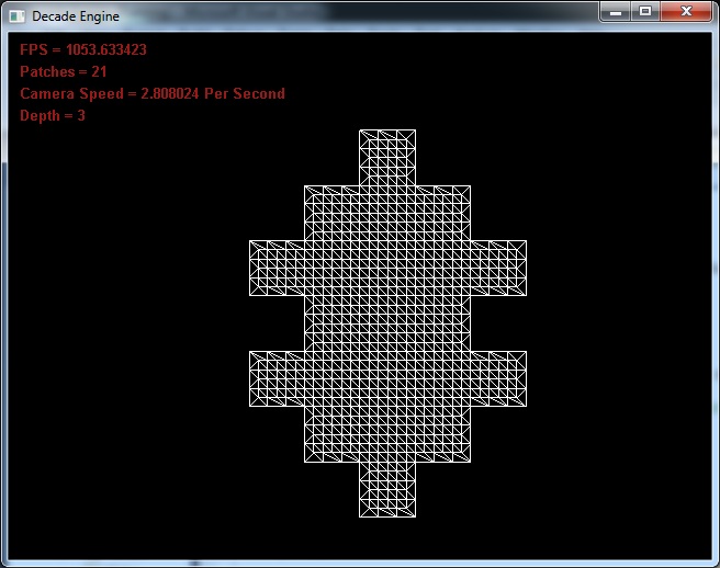
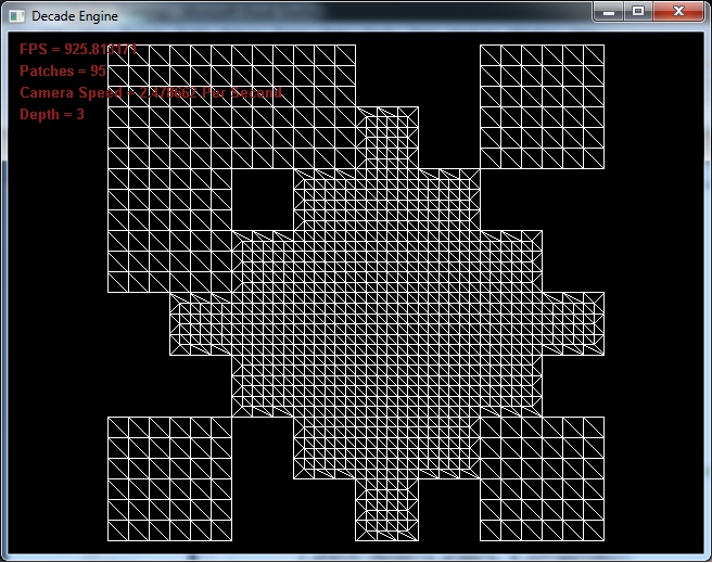
Instead of a patchwork quilt on the planet surface, the terrain LOD (Level of Detail) decreases in concentric circles with its origin at the camera. All patches which neighbour a patch with lower LOD render the corner edge downgraded to the lower LOD preventing any terrain cracks appearing.

In the above pictures the radius of the LOD circle is set to 6.0. This means that the LOD circle has a radius of the length of the patch at this level of detail multiplied by 6.0. This value can be changed at runtime if desired resulting in a higher or lower detail of terrain.
Another change in the example, although not obvious from the pictures is that the planet is no longer updated/rendered from the root node. Now, during the first frame the lead patch is found. This is the patch that is directly below the camera at the correct LOD. Each frame when the planet updates the lead patch moves to one of its neighbours, children or its parent if required. This requires a little more code than simply recursively moving across the patch tree each frame, but should be faster as it removes the processing on many invisible patches (those which are closer to the root of the patch tree but are too low level of detail to meet our needs).
The below video has 3 sections.
- Run-time cube subdivision and application of noise to create planet structure. Patch size is 10x10 quads. To give decent minimum resolution, the lowest possible level of subdividing in this example is 3, with the highest being 16. As the camera moves towards a patch, and gets within range (configured to radius of patch * 5 in this example) the patch subdivides into 4 children which are rendered instead of the parent when the camera is within range.
- Similar to section 1, except when the camera moves away from the patch, the level of detail which is rendered does not reduce. This would allow users to see the size of patches at every allowed level on screen at once, however when far away the patches at level 15 and/or 16 are smaller than 1 pixel so not really visible. Some very basic math will tell us that if the planet in view was earth size (i.e. radius of 6378km) the length of a patch at level 1 would be 7364.67km. At level 16 the patch length is only 0.1123km and with 10 quads per patch length, the max resolution of the planet is just above 1m. By increasing the max allowed depth rendered, or the resolution of each patch, this maximum planet resoultion could be increased to cm level.
- Using frustum culling is not enough to remove any unrendered polygons from the planet. When close to a planet it can look like a flat terrain, just like the earth does for us as we stand on it, but from height it can be seen that the planet is in-fact spherical. With this knowledge it is possible to mathematically remove allot of the planet patches which are on the opposite side of the planet. With Back face culling the API would remove these anyway, however it would be very wasteful to pass these invisible faces down the render pipeline. By using a DotProduct with the LookAt vector of the camera and the Normal of the planet patch translated to model space, it is very simple to ignore these patches.
Version 2 is representitive of a more traditional editor, showing multiple views of the subject. 3 independent views of the terrain can be seen in the video below. Each view maintains its own render state. It is, for example, possible to show one view in wireframe, while the others remain solid or are shown in point form. There is also correct "Screen to World Projection" for each view.
Version 2 also contains some erosion filters. I noticed when editing that the old issue of terrain steps was occuring. By giving the ability to erode or filter the terrain any rough edges are smoothed out.
All application level in the above example is again scripted. On startup the DecadeEngine Sandbox calls the script init function and each frame the HandleInput, Update, Render3d and Render2d functions are called in the script. If anyone is interested in having the script please mail me or comment to this post. Its a little long and boring to publish here.
It should be noted before reading any further that this is the first shader I have ever written. I've used and modified shaders before such as Sean O'Neil's atmospheric scattering (there is a post below somewhere) and some bumpmapping, but all code in this shader is mine and therefore possibly with some rookie mistakes.
Lets first refresh on the very simple texture generation technique currently implemented. The user specifies a list of terrain regions. Each region has texture data, an optimal, min and max height associated with it. For each pixel in the texture being generated the terrain height at that position is queried, interpolated if required (if the texture is higher resolution than the terrain mesh). This height is then compared to all terrain regions and a colour of the pixel is based on the strength of this height within the regions. There are many examples of the results of this algorithm elsewhere in the blog if you have not already seen.
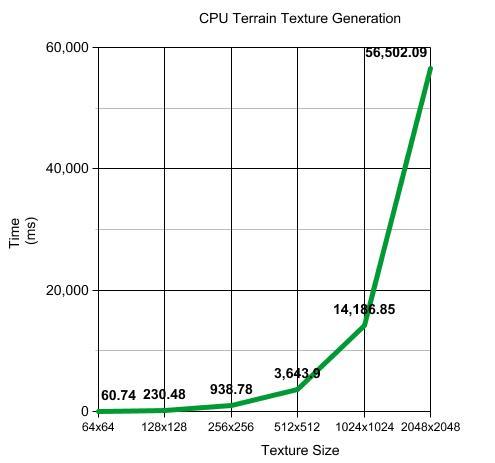
Above can be seen the times used to generate the textures in software. 2048x2048 taking almost 1 minute! My code in this area isn't by any means heavily optimised, but is well written. Its a relatively simple algorithm of iterating though a list and comparing the height value against the region. Previously when procedurally generating a planet at run-time the texture size of choice was 256x256. This provided average detail but with the generation time of about 1 second, a freeze in movement was very obvious.
Now on to the better news....
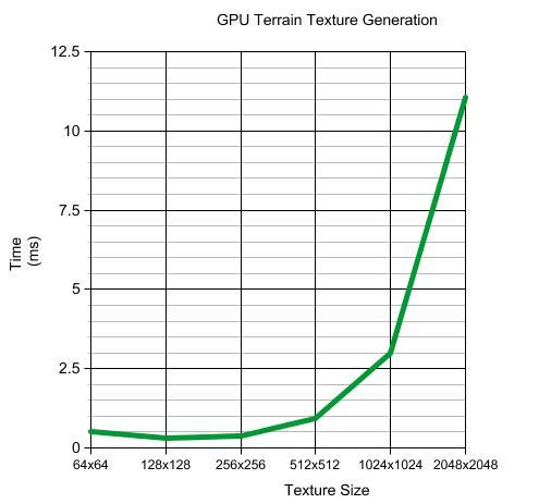
What a difference? These times include the full process of using a the shader
- Binding the Frame buffer so that the texture can be rendered off screen,
- Enabling the Vertex and Fragment shader, binding the textures required.
- Rendering the texture
- Unbinding/disabling everything used during this sequence.
Here is the fragment shader, which does all the work. The vertex shader just passes the vertex down the render pipeline.
struct vOutput
{
float4 color : COLOR;
};
struct TextureRegion
{
float2 startTextureCoord;
float2 endTextureCoord;
float optimalHeight;
float minHeight;
float maxHeight;
};
vOutput Main(float2 texCoord : TEXCOORD0,
uniform sampler2D heightMap : TEX0,
uniform sampler2D terrainTexture : TEX1,
uniform int terrainTextureRepeat,
uniform sampler2D detailTexture : TEX2,
uniform int detailTextureRepeat,
uniform float blendingRatio,
uniform TextureRegion regions[4])
{
vOutput OUT;
//Get the Height
float4 bytes = tex2D(heightMap, texCoord);
float height = ((bytes[0] * 16777216.0f) + (bytes[1] * 65536.0f) + (bytes[2] * 256.0f)) / 1000.0f;
//Strength of this Terrain Tile at this height
float strength = 0.0f;
//Color for this Pixel
OUT.color = float4(0, 0, 0, 1);
int colorset = 0;
//For Each Terrain Tile Defined
for (int loop = 0; loop < 4; loop++)
{
//If the Current Terrain Pixel Falls within this range
if (height > regions[loop].minHeight && regions[loop].maxHeight > height)
{
colorset = 1;
//Work out the % that applies to this height
//If Height = Optimal, then its 100% otherwise fade out relative to distance between optimal and min/max
if (height == regions[loop].optimalHeight)
{
strength = 1.0f;
}
else if (height > regions[loop].optimalHeight)
{
float temp1 = regions[loop].maxHeight - regions[loop].optimalHeight;
strength = ((temp1 - (height - regions[loop].optimalHeight)) / temp1);
}
else if (height < regions[loop].optimalHeight)
{
float temp1 = height - regions[loop].minHeight;
float temp2 = regions[loop].optimalHeight - regions[loop].minHeight;
strength = temp1 / temp2;
}
if (strength != 0.0f)
{
float2 tileTexCoord;
//Tile the Texture Coordinates
tileTexCoord[0] = fmod((texCoord[0] * terrainTextureRepeat), 1.0f);
tileTexCoord[1] = fmod((texCoord[1] * terrainTextureRepeat), 1.0f);
//Recalculate the Texture Coordinates so that they are within the Specified Tile
tileTexCoord = regions[loop].startTextureCoord + ((regions[loop].endTextureCoord - regions[loop].startTextureCoord) * tileTexCoord);
//Get the Color at this Terrain Coordinate
OUT.color += (tex2D(terrainTexture, tileTexCoord) * strength);
}
}
}
if (0.0f == colorset)
{
//Make Pink so that its obvious on the terrain (only for debugging)
OUT.color = float4(1, 0, 1, 1);
}
else
{
//Scale the Texture Coordinate for Repeating detail and get the Detail Map Color
texCoord *= detailTextureRepeat;
float4 detailColor = tex2D(detailTexture, texCoord);
//Interpolate Between the 2 Colors to get final Color
OUT.color = lerp(OUT.color, detailColor, blendingRatio);
}
return OUT;
}
This week I have been using this shader in 2 ways.
- Use as described above, to generate a texture once per terrain patch (will get generated in higher detail when the patch subdivides) and this texture is then used when rendering.
- Use and bind every frame which gives per-pixel texture generation. This has the obvious disadvantage of requiring that the texture data for the terrain is generated each frame, but obviously does so for only the onscreen terrain. It has the nice advantage of not taking up any graphics memory, no need for frame buffers, rendering off screen, etc.... I was getting between 200 and 600 fps using this method.
All the above results were generated on my laptop which has the following.
Renderer: ATI Mobility Radeon HD 3670
Vendor: ATI Technologies Inc.
Memory: 512 MB
Version: 3.0.8599 Forward-Compatible Context
Shading language version: 1.30
Max texture size: 8192 x 8192
Max texture coordinates: 16
Max vertex texture image units: 16
Max texture image units: 16
Max geometry texture units: 0
Max anisotropic filtering value: 16
Max number of light sources: 8
Max viewport size: 8192 x 8192
Max uniform vertex components: 512
Max uniform fragment components: 512
Max geometry uniform components: 0
Max varying floats: 68
Max samples: 8
Max draw buffers: 8
As always comments are welcome and appreciated.
To overcome this a terrain file format was created for decade. This allowed the saving of height data to a binary or text file using multiple bytes per value. With the introduction of shaders into Decade terrain engine, this too has become inadequate. I need to send the height information to the shader, along with the source tiles so that the procedural terrain texture can be created. The only feasible way to send this height information to the Graphics Card is in a texture, but the grey-scale implementation did not have high enough detail.
Solution? Combine the texture implementation with the multi-byte file format. To do this I split the floating point height position across the 3 color bytes using some simple bit shifting.
Using 3 bytes it is possible to represent 16777216 unique values (256x256x256). In the following example I want to maintain 3 digits after the decimal separator. This allows me to have terrain heights from 0.000 to 16777.216 which should be suitable for most procedural planets. It is of course possible to make the number of decimal digits configurable.
To convert a floating point height into 3 bytes (used in the texture rgb).
//Get the Height at the current Terrain Position
float l_fHeight = get_HeightAtPoint(l_iXPosition, l_iYPosition);
//Convert to an int. Multiply by 1000 to keep 3 decmial places.
int l_iColor = (int)(l_fHeight * 1000);
//Seperate into 3 Bytes
l_ucRed = ((l_iHeight >> 16) & 0xFFFF);
l_ucGreen = ((l_iHeight >> 8) & 0xFF);
l_ucBlue = l_iHeight & 0xFF;
and to convert 3 bytes back into a float, with 3 decimal places is as easy as
l_fHeight = ((l_ucRed << 16) | (l_ucGreen << 8) | l_ucBlue) / 1000.0f;
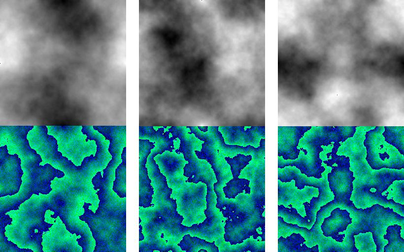
Above is a sample showing grey-scale height maps and their equivalent 24bit height maps. When I first saw the new maps, I thought there was a bug, and there would be rough edges in the terrain, due to the sudden color changes within the texture, however it loads correctly and terrain detail is maintained.
Over the past week or two I've been researching shaders. I have decided to add support for CG and CGFX to Decade. My first task with this will be to move the procedural texture generation to the GPU. This should hopefully vastly speed up this area of the engine allowing much smoother planet generation.
Having reviewed the Decade code with a fresh mind, some housekeeping is first required. Cleaning up interfaces and improving segments before building upon. Within the next week I hope to have some comparisons between generating the textures on the CPU and the GPU. Not having much experience using the GPU for this type of processing I am unsure what to expect but from reading other blogs regarding Planet and Terrain generation I am confident that it is the right approach to take.
The video below shows my sandbox terrain editor. This is running in Engine Real time. By changing the size of the target area and using the mouse wheel it is possible to raise or lower segments of terrain. As the terrain changes the terrain texture is recalculated (for modified areas).
Key features:
- Dynamic Vertex Buffer Object updating when terrain is updated
- Dynamic Texture Updating when terrain is updated (from a set of source textures and height values (Optimal, Min, Max)
- Screen to World projection allowing Decade to know where in the world the user is selecting with the mouse.
- High level functionality of demo is 100% scripted (which calls Engine functions bound to script engine)

A GUI system is also in development. This system is based on my experience of C#. It is possible to register events for each GUI component on the engine or script level. These events are fired under the specified circumstances. e.g. Mouse Enters, Mouse Leaves, MouseLeftClicked etc...
Version 2 of the Terrain Editor should make use of this GUI system and also support features such as
- Adding areas of Water
- Adding areas of vegetation
- Erosion Filters on selected area or whole terrain
- Texture splashing for better terrain details. (Roads, coast line etc...)
No longer is Decade contained within 1 project. Logically dividing the sections up into DecadeUtilities, DecadeScript, DecadePhysics, DecadeInput, DecadeOnline, DecadeGraphics and DecadeEngine, a DLL has been created for each resulting in a complete game engine. Another advantage of this is that each of the components resides behind an "Abstraction Layer" therefore allowing me to change individual components such as graphics API, physics engine without having to recompile and deliver the whole game.
The names of the components descript pretty well what functionality is contained however for clarity I will give a brief overview starting at the bottom.
DecadeUtilities contains random functionality which does not meet the criteria of the other DLL's as well as functionality which is common to many of the DLL's higher up the chain. e.g Math, I/O
DecadeScript contains methods for loading and executing scripts at run time. As well as Decade calling functions within the script, most of the objects in the Decade suite of DLL's have been bound to the script engine allowing powerful control of the game engine from the script level. In the long term this will allow allot of customisation and add on capability to games made with the Decade Engine. Supported script engines are Game Monkey with LUA support currently being added.
DecadePhysics as the name suggests contains a physics engine. In keeping with the other DLL's in the Decade Suite all the physics engine functionality is contained within an "Abstraction Layer" which will allow support for other physics engines to be added quickly and easily. ODE is the current 3rd party physics engine supported by Decade.
DecadeInput contains functionality for all input methods. Keyboard, Mouse and Joystick/Joypad support are easy to add to your game project and with simple bindings to the script engine it takes a matter of minutes to map your keypress's or mouse moves to your desired functionality.
DecadeOnline is the encapsulation of online communication methods for multi-player online games. Offering you the possibility to create a server or client with ease and communicate over TCP or UDP.
DecadeGraphics contains all the graphics API functionality required in a 2D or 3D game, from creating an index or vertex buffer, loading a texture to graphics memory, executing a vertex or fragment shader. DecadeEngine currently uses OpenGL however a DirectX version of this DLL should be available in the near future.
DecadeEngine is the main interface to the Decade suite. This layer contains all the 2D and 3D engine functionality such as loading a texture, loading a mesh, creating a terrain or planet, lights, shadows etc....
In the above video the planet is made up of 125x125x6 vertices's and the moon from 65x65x6 faces. There is currently no complete LOD functionality. When fully implemented each face recursively subdivides into 4 faces of equal area, resulting in the level of detail of each face increasing by a level of 4 with each divide.
With some clean programming, a vertex should never have to be calculated more than once (unless the player moves a distance away and the section is deleted from memory). The parent will populate each of its children with the relevant subset of its data, and only the unknown sections calculated, resulting in lower memory usage as well as faster run time higher LOD generation.
In continuation to the Procedural Sphere entry I made a few months ago, and from inspiration by the ongoing work of Jelly Edwards I decided to look into further developing the sub-dividing cube with procedural noise in order to make a planet.
The noise algorithm used is Fractional Brownian motion (fBm) which is a form of Perlin Noise.
A good article about fBm in relation to procedural planets can be seen here. This work was carried out by Sean O'Neill who has also contributed allot to atmospheric scattering.
Very early and basic attempts at a procedural planet can be seen below. For the purpose of illustrating the deformation of the sphere I have magnified the hills and valleys on the planet, which results in what looks like an asteroid or moon.

There are some key failings with this version. It is slow to render as the vertex and index buffers and built each frame. The whole planet is the same Level of Detail (LOD). This is ok for distance viewing, however as the camera approaches the surface of the planet, rendering the entire scene at a high LOD would cripple even the most powerful of computers.
Many of the techniques learned when researching and implementing my terrain system will be used here.
- Dividing the planet surface into patches
- Each Patch manages their own LOD (through subdivision and creation of child patches) based on distance from the camera.
- Each Patch maintains its own Vertex Buffer, while sharing a group of Index Buffers (to cover neighbour patches with different LOD's)
Allot of my terrain modules can be reused, with perhaps a little added functionality, so I hope that, time permitting, adding these features will not take too long.
A good explanation of the .md5mesh file format can be found here and a similar explanation of .md5anim can be found here.
After reading the two file format descriptions specified above as well as a refresher on quaternions it was not too difficult to parse the files and create the mesh and animations.
In order to make Decade's MD5 support as complete as possible it supports multiple loading methods which are specified through a flag parameter in the Load function. One can build hardware/software vertex and index buffers for each specified frame at load time or they can be populated when required.
If an animation does not have a high enough count of frames per second, Decade can calculate additional frames using the mesh/anim data along with quaternions and slerp.

Above is a non shaded, non shadowed terrain. This is the control image to which the next 2 results can be compared. In this normal method a height map is procedurally generated and the terrain texture is then created from this height map and a set of layer textures.

For slope lighting an extra step is added during the terrain texture generation.
For each vertex of the terrain, the neighbour vertex in a specified direction is checked. If it is higher than the current vertex shade is applied. This is a relatively fast technique. In a height map of 512x512 the number of comparisons is 262144.

Shadow texture generation is an extension of the slope shading technique. Instead of checking the immediate neighbour a ray is cast from the current vertex to a specified light position. For every step along the ray the height of the terrain at this point is checked, and if it is higher than the ray shadow is applied to the original vertex. (i.e. there is no direct line of light between the light source and the vertex). In my opinion this produces more realistic results and will combine well with shadow maps or shadow volumes but it is allot slower than the previous methods. To calculate the shade applied to each vertex in the shown 512x512 terrain 45556293 checks were required, which took 27 seconds.
This could probably be improved so that the terrain is checked at a lower resolution, with an approximate shade applied to the "in-between" vertices. This would allow the light source (probably the sun in an outdoor scene) to move.
Decade Blog is 1 year old today. 10% of the way through its life!
Slope Lighting
Reciently my long time friend and arch nemisis Jelly Edwards, who is also now my blog enemy, has started a DX10 terrain engine and his slope lighting effect was impressive especially considering the ease at which it can be added and the free cost of this effect.
Slope lighting is calculated during texture generation therefore has no cost during runtime. Each vertex in the height map is checked against its neighbour in the direction from which the light is coming. If the neighbour is higher than the current vertex shade is applied based on the difference in height (how much the terrain is facing away from the light).

I am hoping that this effect will not be used in the majority of cases, however it is a nice addition to enhance the terrain on computers which do not have the power to do real time shadows.
Long overdue I have fixed the problem. I will briefly try and recap the issue. Segments of the terrain which are further away from the camera are rendered at a lower level of detail than those which are closer. When a patch gets a distance from the camera the level of details halves. Since every second vertex in the lower level of detail is missing this can result in cracks in the terrain. The image below shows this up close. This situation is not realistic because the patch joins will be a distance away from the camera however even at distance it is possible that artifacts would be visible.

In order to overcome this problem I have removed every second vertex along the edge of a patch which has a higher level of detail. This is all calculated during load time. At run time each neighbour of a patch being rendered is examined and a bitmask is calculated accurately describing the surrounding area. This bitmask is then used to offset into an IndexBuffer array, using the correct buffer with no run time calculation required. A more complete description of this can be found in the previous blog entry.

As can be seen above, there are now no visible joints between patches of differing detail, resulting in a more natural terrain.
General Update
In the past month I haven't had allot of time to complete 'Parallel Split Shadow Maps', so this is still in a limbo state. They sort of work however sometimes the scene is a mess and other times there are unknown artifacts.
While making the 2d fluid dynamics demo, with the PlayFirst SDK, I was impressed with their usage of LUA scripting. I have researched this topic a little and feel that I will add support for Game Monkey to Decade. As with the graphics and physics layers the script engine will also be extrapolated away so I can, at a later date, add support for another script engine.
I have also added joypad support to Decade to avoid always having to use the keyboard and mouse. DirectInput was used for this so this functionality will not be added to the Ubuntu version any time soon, or until I at least figure out how to do this in Linux.
I am delighted to announce that a friend has at last got on the game engine band wagon and started his own terrain engine called Jelly Engine. His ultimate goal is to generate a procedural universe. Please have a look at this blog and give him grief on how bad his engine is, even though it would be a lie.
Shadows
Before giving some detail on my shadow map implementation I will briefly describe why I have bypassed Shadow Volumes for now. Shadow Volumes are created by calculating a silhouette of the mesh from the lights point of view. This silhouette is generated from the raw mesh data. The low poly trees currently used in Decade consist of colour keyed faces. The resulting Shadow Volume generates a shadow of the full face and not just the visible (non blended area). Below is a faked image which shows the shadow that would be generated using the Shadow Volume technique. Notice that the shadow for the tree remains the same regardless if colour keying is enabled or not.

Shadow Maps generate shadows by rendering the scene from the lights point of view and saving the depth buffer to a texture. This texture is then used to shadow the scene. The advantages that Shadow Maps have over Shadow Volumes are
- No colour keying issues
- Complex geometry does not affect the performance of the algorithm. The scene rendering should be efficient as it must be rendered 3 time per light
- From Lights point of view. Depth Buffer saved to Texture
From Cameras point of view with only ambient lighting.
From Cameras point of view with light enabled and Shadow Map applied.
The complexity of the geometry is of much higher importance in Shadow Volumes because as mentioned previously the silhouette is generated from the raw mesh data

Due to the limited resolution of the texture map holding the depth/shadow data Shadow Maps can and usually do result in very aliased shadows. In the image below the light is only 75 units from the scene however it is very evident from looking at the car shadow that the shadow quality is very low. The right image shows the depth buffer from the lights point of view which is used to render the shadows.

Below can be seen how the Shadow Mapping technique becomes unusable as the light source moves further away from the scene or as the scene boundary grows. With less shadow map pixels used to represent the shadow of the same area of space the shadow loses form and any relationship with the casting object.

These issues make the Shadow Mapping technique inappropriate for rendering any large outdoor scene. Further research has shown that Shadow Mapping has some advanced friends such as Parallel Split Shadow Mapping. (PSSM). The PSSM method involves splitting the frustum into several parts along the eye vector, and rendering a separate Shadow Map for each split. This allows the area closest to the camera to use higher resolution shadow maps and with the resulting Shadow Map stretched over a much smaller area, less aliased shadows are possible.
Ubuntu
Instead of making my desktop dual boot, I decided to try and use Microsoft Virtual PC, which is also free to download. It was a very easy to create the virtual PC, virtual hardisk and install Ubuntu. I can now access my Ubuntu installation from within my windows environment getting the benefits of both systems.

It took a little effort to get networking enabled, my router requiring some setting changes however once this was complete it was again a simple process to connect over the local network and access the shared drives on my Windows PC. With this setup I hope to use the same source base for Win Decade and Ubuntu Decade.
My first job after leaving university was in a HPUX environment however being a number of years ago I have forgotten allot of the basics. This morning I created the obligatory "Hello World" C++ program, but am having problems building OpenGL and SDL projects.
Decade Meets ODE
Having messed around with ODE (Open Dynamics Engine) a few years ago I decided that I would start with this free physics engine. I am trying to use the same approach in adding the physics as I did with the graphics. I have implemented an extrapolation layer between the game engine and the physics engine with the hope that in the future I can add support for other physics engines without having to change too much of the game code.
Refreshing myself with the theory of ODE last week I have now started to modify Decade. Up to now all transformations, rotations etc.. in Decade were stored as Eulars. ODE rotations are matrix based so rather than have converter functions to change between Eular->Matrix and Matrix->Euler I modified the Decade core so that each object builds its own Model View Matrix. The Projection and View matrices are also build and handled by Decade. Although a little more complicated to code and read this approach does have some advantages. For an object which is static in the world its matrix can be built once, reused time and time again and doesn't have to be updated until the object moves. Using the glRotate, glScale and glTranslate functions this matrix was built for each object every frame.
-
Properly fixing cracks in terrain
-
Priority Rendering Queue
-
Octree V Quadtree
-
ROAM Terrain
-
Finish Shadow Volumes and Parallel Split Shadow Maps
and after that I need to continue with my future to do list
-
Scriptable Particle System and Editor
-
Planet Generation
-
Some small tech games (Golf, racing etc...)
Atmospheric Scattering
As always there is a list of improvements to make. The planet is currently rendered in software, each face rendered separately. There is also no culling. Adding hardware acceleration and efficient culling should greatly improve performance. The subdivided implementation of the sphere allows easy culling of vast numbers of faces with a few checks.
Procedural Sphere
To maintain Decade's procedural capability and to remove the issues with the previous implementation I created my own Sphere function by recursively subdividing a cube until the required resolution was achieved.
Below the two solutions can be seen side by side. On the left is the Sphere created with gluSphere or loaded from a file. The vertex compression is immediately obvious. The size of the face depends on which segment it exists, with faces getting smaller closer to the poles. On the right is my procedurally generated sphere. As you can see there is no vertex compression at the pole. In fact no pole is visually obvious. Due to the subdividing nature of the algorithm each face in the sphere is the exact same size.

I believe I may have achieved allot more than just creating a sky dome with this implementation. Creating a universe with procedural planets has always been on the wish list for Decade but I never knew where to begin. The recursive subdivision appears to be an ideal solution for this. It has level of detail and efficient culling properties automatically built in.
The level of the quad tree rendered defines the level of detail of the planet. Since the root of the planet is 6 quads, it is easy to bounds check these against the frustum and quickly remove unseen areas of the planet and the same process can be repeated for each of the child levels of the quad tree.

By using the above algorithm along with some height maps I believe rendering a full planet should be possible. I look forward to the day when I can roam a planet in Decade then jump in a space ship, fly away and land on another planet.
Oil Painting

and here is Decade as an Oil Painting.
I am happy with the results, although now a little unsatisfied that the manipulation is not real time. I'm not sure of the possibility of writing a Pixel Script to do this in real time because it requires sampling multiple pixels in order to create the smudged Oil Paint effect. Despite this I still plan to at least try and implement an Oil Painting script sometime. It would be nice to make a game where it appears that the whole world is painted, and perhaps the levels of the game could be based on classic painting by Da Vinci, Picasso etc.
I have also been working on Atmospheric Scattering this month but because of my other commitments have not yet fully integrated with Decade. I will try and get a video update soon to at least give a taster of my progress.
The other day I found a shortcut to my old website. It has been almost 3 years since it was updated. Hosted on an Irish telecoms provider, I do not seem to be able login to my account from outside Ireland so it has remained static since I left. It has some fond memories for me. This was my start in game programming as a hobby. The host where my game demos were stored is no longer active so you cannot download anything. If you would like to try anything leave a comment and let me know. I will then find the game in my archive and upload it.
'Multimedia' 카테고리의 다른 글
| InfoEra - Undet point cloud processing software for object analysis, 2D drafting and 3D modeling - Undet for Point cloud (0) | 2012.05.01 |
|---|---|
| Update 10.1.0 - April 3rd 2012 [Orbit Knowledge Base] (0) | 2012.05.01 |
| Animation of OpenStreetMap Edits in 2008 (0) | 2012.04.22 |
| Google Maps and Its Competitors (0) | 2012.04.22 |
| Dr Dave Technology Prescriptions (0) | 2012.04.15 |
| The making of Transformers 2 (0) | 2012.04.08 |
| Tribute to Transformers The Movie: 86 Inspiring Artworks (0) | 2012.04.08 |
| NVIDIA vs AMD 워크스테이션 그래픽카드 (1) | 2012.04.05 |
| Google Driving-simulator (0) | 2012.04.04 |
| OpenTK - (Open Toolkit library) (0) | 2012.04.02 |